Wiring spec
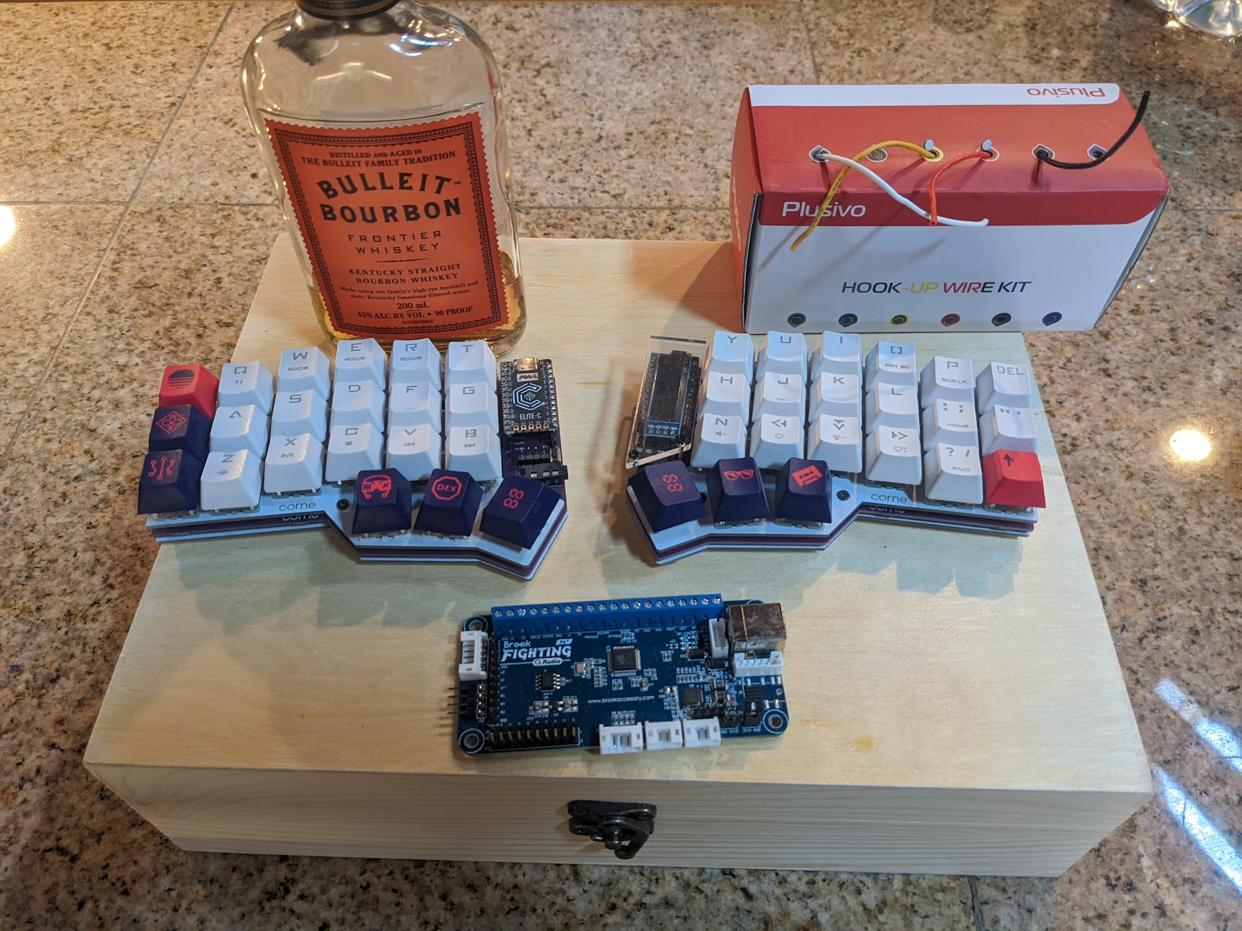
Bench photo
The controller started as a wiring layout: Brook Universal Fighting Board, mechanical switches, a wood enclosure, and hookup wire staged before final assembly.
Notes
Each mechanical switch has two electrical sides. One side goes to a labeled signal input, such as 1P, 2P, UP, or START.
The other side goes to GND. Because the board uses common ground, those ground wires can be chained from switch to switch.
The clean rule: signals stay separate, ground can be shared.
Source
Reference docs
The wiring labels come from Brook’s Universal Fighting Board product page and user guide. The diagram here is simplified for this build log, not a replacement for the official manual.